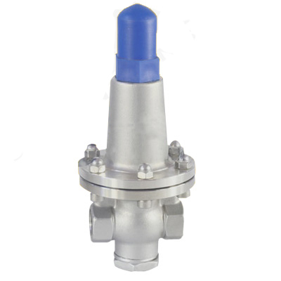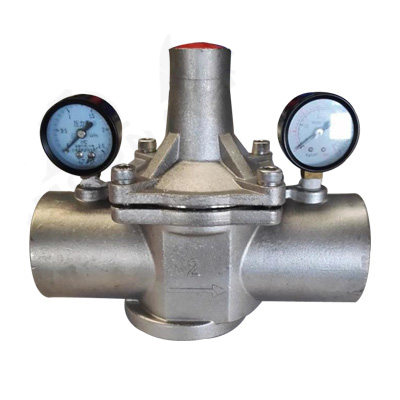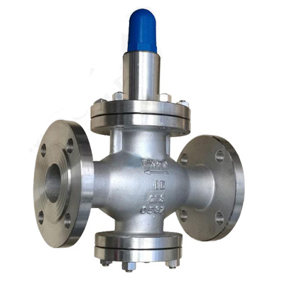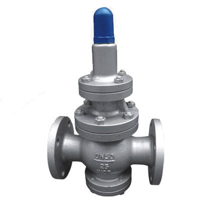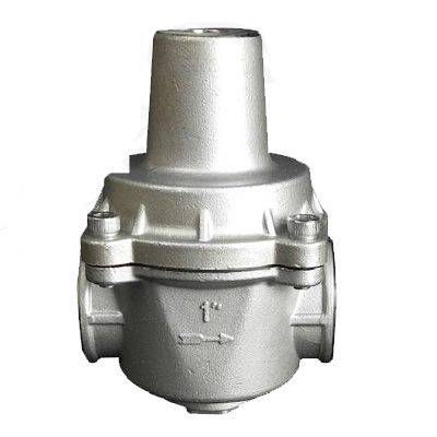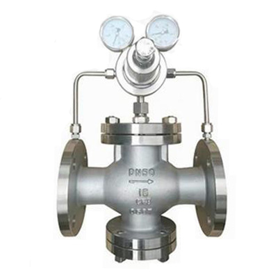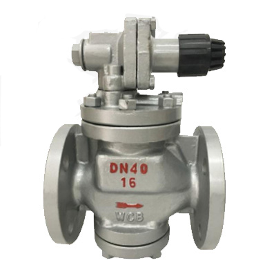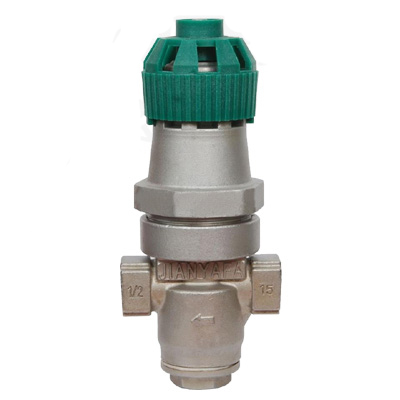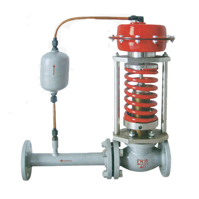
ZZYP self-operated pressure reducing valve
Main modelSingle seat pressure closed typeZZYP-16~64BSingle seat pressure closed typeZZYP-16~64KTwo-seater press-to-close typeZZYN-16~64BTwo-seater press-to-close typeZZYN-16~64KSleeve pressure closed typeZZYM-16~64BSleeve pressure closed typeZZYM-16~64KNote:1. Pressure-closing type is used fo...
Main model
| Single seat pressure closed type | ZZYP-16~64B | Single seat pressure closed type | ZZYP-16~64K |
| Two-seater press-to-close type | ZZYN-16~64B | Two-seater press-to-close type | ZZYN-16~64K |
| Sleeve pressure closed type | ZZYM-16~64B | Sleeve pressure closed type | ZZYM-16~64K |
Note:
1. Pressure-closing type is used for pressure adjustment behind the valve. When the pressure behind the valve rises, the valve is closed to achieve the purpose of reducing pressure and stabilizing.
2. The pressure opening type is used for pressure adjustment behind the valve. When the pressure behind the valve rises, the valve opens to achieve the purpose of pressure relief and stabilization.
The main technical parameters
| Nominal diameter DN (mm) | 20 | 25 | 32 | 40 | 50 | 65 | 80 | 100 | 125 | 150 | 200 | |||
|---|---|---|---|---|---|---|---|---|---|---|---|---|---|---|
| Valve seat diameter DN (mm) | 10 | 12 | 15 | 20 | ||||||||||
| Rated flow coefficient Kv | 1.8 | 2.4 | 4.4 | 4 | 11 | 20 | 30 | 48 | 75 | 120 | 190 | 300 | 480 | 760 |
| Allowable pressure difference (MPa) | 2.5 | 2.0 | 1.6 | 1.0 | ||||||||||
| Nominal pressure (MPa) | 1.6 4.0 6.4 | |||||||||||||
| Inherent flow characteristics | Open fast | |||||||||||||
| The minimum pressure difference P (MPa) to ensure the normal operation of the pressure regulating valve | 0.05 | |||||||||||||
| Pressure range (KPa) | 15~50 40~80 60~100 80~140 120~80 160~220 200~260 240~300 280~350 330~400 380~450 430~500 480~560 540~620 600~700 680~800 780~ 900 800~1000 900~2000 | |||||||||||||
| Working temperature °C | Liquid ≤140; Gas ≤80; with condenser and heat sink ≤350 | |||||||||||||
| Suitable medium | Gas, steam, low viscosity liquid | |||||||||||||
| Flange size and type | PN10, 16, 40GB9113-88, PN64JB/T7-94; PN10, 16 male, PN40, 64 female or other standard flanges according to user requirements (such as ANSI, JIS, DIN and other standards) | |||||||||||||
| Structure length | According to GB12221-89 standard | |||||||||||||
| Can be equipped with accessories | Condenser (used when the medium is steam), heat sink, etc. | |||||||||||||
| Actuator signal interface | Internal thread M16×1.5 | |||||||||||||
Note: The pressure range can be designed according to user requirements.
[ZZYP self-operated pressure reducing valve] main performance indicators Note
| control precision% | ±8 | |||||||||||
|---|---|---|---|---|---|---|---|---|---|---|---|---|
| Allowable leakage | Hard seal (L/H) | Single seat (grade Ⅳ): ≤10-4 rated capacity of valve: double seat, sleeve (grade Ⅱ), ≤5×10⁻³×rated capacity of valve | ||||||||||
| Soft seal (ml/min) | DN (mm) | |||||||||||
| 20 | 25 | 32 | 40 | 50 | 65 | 80 | 100 | 125 | 150 | 200 | ||
| 0.15 | 0.3 | 0.45 | 0.6 | 0.9 | 1.7 | 4.0 | 6.75 | |||||
Dimensions and weight
ZZYP self-operated pressure reducing valve]pressure adjustment steps
Follow the steps below to slowly turn the adjusting screw to complete the setting. Improper adjustment operations may cause water hammer or banging sound, etc., which may cause damage to the pressure reducing valve or other equipment.
(1) Close the front and rear shut-off valves of the pressure reducing valve. Under the condition that the safety valve does not jump, open the bypass line shut-off valve and keep it for sufficient time to complete the purging and removal of foreign matter or rust layer in the pipeline by the circulating medium. . After the purge is complete, close the bypass line shutoff valve.
(2) Slowly open the shut-off valve installed in front of the pressure reducing valve, and adjust the opening degree of the shut-off valve after the pressure reducing valve to maintain a small flow through the pipeline.
(3) Loosen the lock nut, slowly turn the adjustment screw, and observe the pressure gauge behind the valve until the required setting is planted (clockwise rotation pressure rises, counterclockwise rotation pressure drops). For models with handles, since the handle is in the self-locking position under normal conditions, when adjusting the pressure, you should first press down on the handle, loosen the self-locking, and then slowly turn the adjusting screw, and observe the pressure gauge closest to the valve until The required setting is planted (when the handle is turned clockwise, the pressure behind the valve rises; when the handle is turned counterclockwise, the pressure behind the valve drops.).
(4) Slowly open the pressure reducing valve and then shut off the valve, and follow the steps
(3) Further adjust the pressure after the valve until the required setting is planted.
(5) After finishing the adjustment, tighten the lock nut. For models with handles, pull out the handle and use the internal device to lock it; if the handle is not locked, turn the handle left and right to complete the self-locking action.
Reference example of pressure reducing valve installation configuration: